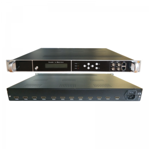
EN04 SD Encoder Modulator
Short Description:
1 Product Overview
The EN04 series is the latest cost-effective SD encoder modulator with IP/ASI output all-in-one device. It supports 4 / 8 channels CVBS input, 1 channel Gigabit IP input/output; 2 independent ASI outputs, 4 (ATSC、ISDBT、DTMBT、DVB-C/-T) output, 4 MPTS output, and SPTS output. With high integration, great performance and low cost, Integrating a complete front-end system functions, this device is highly welcomed in small digital TV transmission systems such as hotels, clubs, hospitals, etc.
2 Key Features
l 4 / 8 channels CVBS input
l 1 Gigabit IP input/output, MPTS output, UDP/RTP protocol (multicast)
l Support ATSC/ISDBT/DTMBT/DVBC/DVBT RF output
l Support 1* ASI input
l Support 2* ASI output independently
l LCD display and Buttons operation
l Web network management
l Support online software upgrading
3 Specifications
| Input | CVBS (4/8 CVBS) | ||
| 1*ASI input | |||
| 1 IP Gigabit IP input | |||
| Output | 4 (DVB-C/DVB-T/ATSC/ISDBT/DMBT) RF outputs | ||
| 2 separate ASI output | |||
| IP output (SPTS, MPTS ), UDP/RTP protocol | |||
| Video Encoding | Encode Format | MPEG-2 AVC | |
| Input Port | CVBS A/V | ||
| Input Resolution | 1280×720P/720x576i/720x480i @50/59.94Hz | ||
| Output Resolution | 1280×720_30P,720x576_25P,720x480_25P | ||
| Code Rate | 1Mbps~13Mbps(each port) | ||
| Rate Mode | CBR、VBR | ||
| Audio Encoding | Encode Format | MPEG1 Layer2 | |
| Sample Rate | 48KHz | ||
| Bit Rate | 64kbps ,128Kbps,192kbps,224kbps,256kbps,320kbps,384kbps | ||
| System | Web management and support online updating | ||
| Chinese/English operation interface | |||
| Physical Parameters | Dimension | 482mm×410mm×44mm | |
| Weight | 8kg | ||
| Operating temperature | 0~45℃(Working);-20~80℃(Storage) | ||
| Power | AC100~240V,50/60Hz | ||
| Power Consumption | <90W | ||
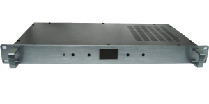
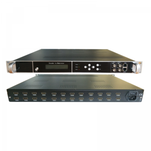
4 Structure
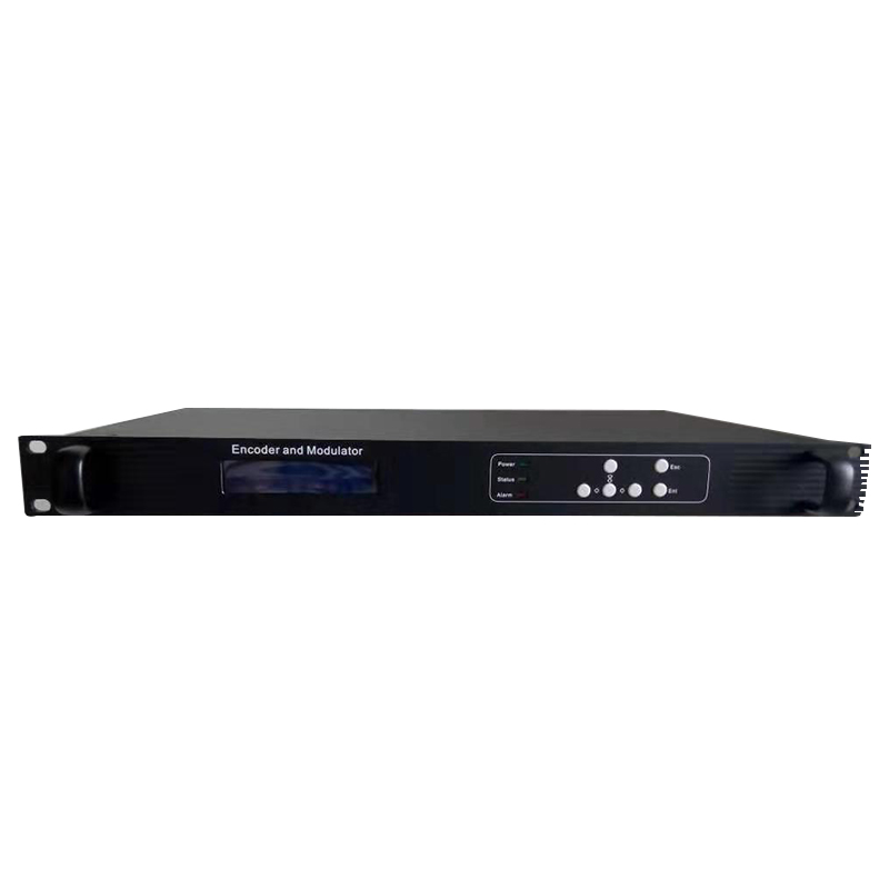
Front panel:
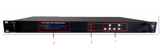
| 1. | LCD Display |
| 2. | Indicator lights |
| 3. | Buttons |
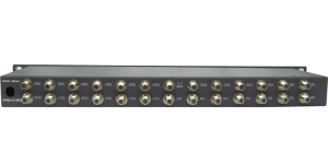
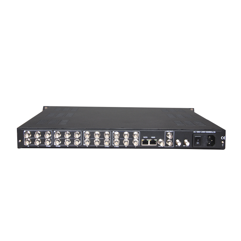
Rear Panel:
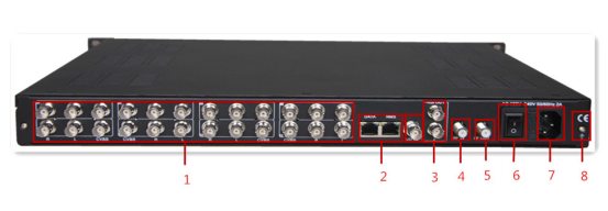
| 1. | CVBS A/V input |
| 2. | NMS、DATA Input/Output |
| 3. | ASI in/out |
| 4. | RF in |
| 5. | RF out |
| 6. | Power switch |
| 7. | Power in |
| 8. | Grounding |