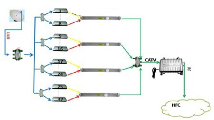
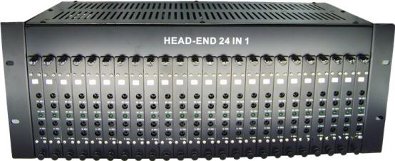
The GG-24M is a 4RU rack mounted chassis that allows for installation of up to 24 pieces microprocessor-controlled fixed mini-modulators. Built-in active combiner eliminates unnecessary cabling and potential connection problem and ensures high output level.
All modulators are perfect factory set to desired channels and proper offset.
FEATURES
1. Switching power supply for installation flexibility and precise voltage regulation
2. Two cooling fans for long life performance
3. 45dBmV chassis output level, no need extra combiner
4. SAW (surface acoustic wave) filtering on IF for superior in band C/N
5. Front panel access controls enables easy setup
Specification
|
Frequency |
47~860MHz |
|
Output Level |
≥105dBμV |
|
Output Level Adj. Range |
0~-20dB (Adjustable) |
|
A/V Ratio |
-10dB~-30dB (Adjustable) |
|
Output Impedance |
75Ω |
|
Spurious Output |
≥60dB |
|
Frequency Accuracy |
≤±5KHz |
|
Output Return Loss |
≥12dB(VHF); ≥10dB(UHF) |
|
Video Input Level |
1.0Vp-p(87.5% Modulation) |
|
Input Impedance |
75Ω |
|
Differential Gain |
≤5%(87.5% Modulation) |
|
Differential Phase |
≤5°(87.5% Modulation) |
|
Group Delay |
≤45 ns |
|
Visual Flatness |
±1dB |
|
Depth Adjust |
0~90% |
|
Video S/N |
≥55dB |
|
Audio Input Level |
1Vp-p(±50KHz) |
|
Audio Input Impedance |
600Ω |
|
Audio S/N |
≥57dB |
|
Audio Pre-emphasis |
50μs |
|
Dimension |
19 Inch 4U standard Size |
PANEL ILLUSTRATION
Front Panel
5 4 6 2 1 3 7
1. RF level adjustment (0-20dB)
2. A/V level adjustment (-17dB preset)
3. Channel sticker
4. Volume control (the volume increases by turning clockwise)
5. Video modulation depth adjustment (the modulation depth increases by turning clockwise)
6. Power indicator (green)
7. Locker to fix the mini modulator inthe chassis.
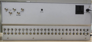
REAR PANEL
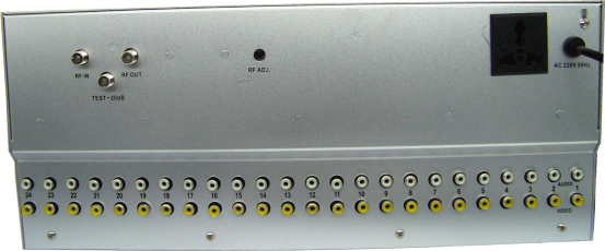
1. Power plug (220Vac In)
2. Power socket (220Vac Out)
3. RF output (F-connector female)
4. Audio Input (RCA Female)
5. Video Input (RCA Female)
6. RF Input to accept (loop) RF out from another modulator
7. Testing ports -20dB
8. RF output level adjustment for whols 16 channel combined
GENERAL OPERATION
1. Connect the standard audio and video cables to the audio input and video input socket on the rear panel respectively.
2. When using one modulator only, insert the power plug of the modulator to a power supply socket directly. When using more than one modulators, you can choose to insert the first modulator’s power plug into the next modulator’s power socket, and so on. Remember to insert the last modulator’s power plug into a power supply socket.
3. Connect the RF Output on the rear panel to the Channel Mixer of the CATV head-end equipment.
4. Adjust the output levels to make the output levels of different modulators almost equal.
5. Adjust the frequency deviation and video modulation depth to obtain best sound and picture.
6. The A/V has been preset before sold. Do not attempt to adjust the “A/V” in case of unnecessary.
How to combine 24 in1 modulator with its extra combiner?
1st UNIT
2nd UNIT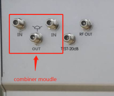
FINAL OUTPUT OF 2 UNITS OF 24 IN 1 MODULATOR TOTAL 48 CHANNELS.
NOTICE
1. Avoid storing in a damp place.
2. Be sure to operate carefully since the modulator has no power on/off switch.
3. Power loop and RF loop should not be more then 5 pcs.
4. Any problem, please resort to the supplier for help.
Post time: Jul-04-2019